 Language


More Language
Language
We are a professional bending machine manufacturer with over 10 years of industry experience. Today, we would like to introduce the design of an auxiliary tool for rapid mold positioning:
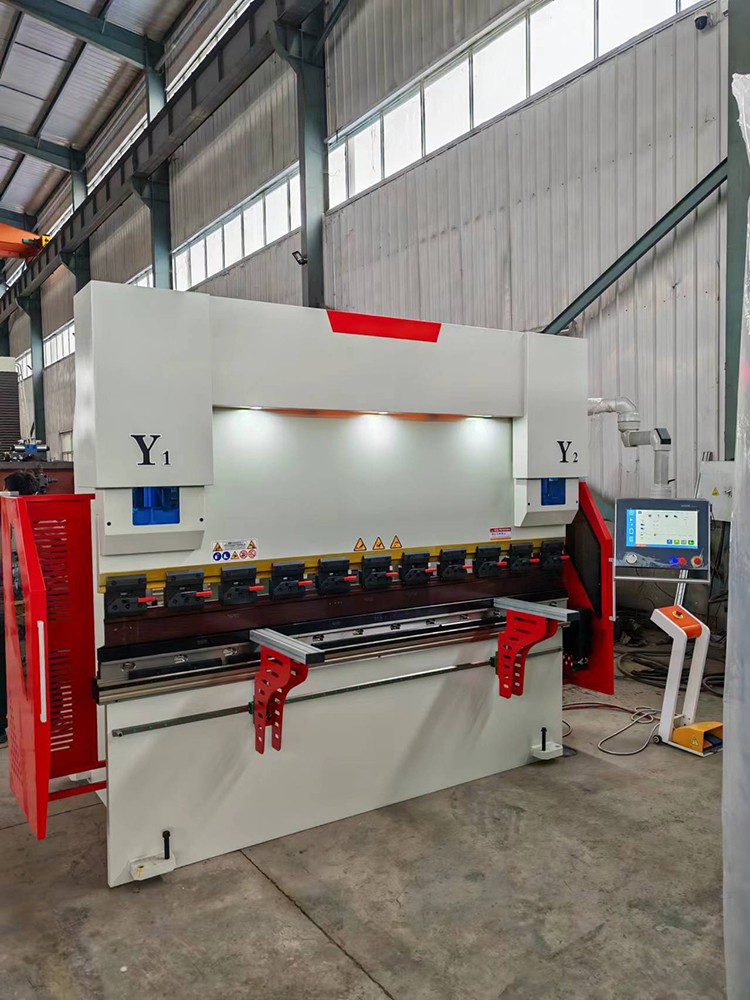
The accurate positioning of bending machine molds directly affects processing accuracy and efficiency. Traditional positioning methods rely on manual measurement, which is time-consuming and prone to errors. This article introduces a design scheme for a specialized auxiliary tool that simplifies the positioning process, improves repeat positioning accuracy, and is suitable for various bending processing scenarios.
1. Design Requirements Analysis
The core requirements for mold positioning are positional accuracy and operational convenience. The tool must ensure that the alignment error between the upper and lower mold centerlines does not exceed 0.1 millimeters, while also accommodating molds of varying thicknesses. Structural strength must be capable of withstanding vibrations and impacts during the bending process, and material selection should prioritize wear resistance for long-term use.
In terms of human-machine interaction, the tool should enable one-handed operation, with a weight controlled within 2 kilograms. The visual indication system must be clearly visible and accurately identifiable even under workshop lighting conditions. Safety design requirements include avoiding interference with moving parts and incorporating anti-disengagement structures as basic elements.
2. Mechanical Structure Design
The main frame is made of high-strength aluminum alloy profiles and has an overall door-type structure. T-slots are provided on the crossbeam for installing various functional modules. The columns are embedded with scale rulers with a minimum scale of 0.5 mm, and the ruler surface is treated to prevent glare. A magnetic base is installed at the bottom, and the suction force can be adjusted to suit the work surface of different machine types.
The positioning module includes a bidirectional fine-adjustment mechanism. The horizontal direction is driven by a precision ball screw, with an adjustment range of ±15 millimeters, and is equipped with a digital readout. The vertical direction uses a wedge block structure, controlled by a knob for lifting and lowering, with an adjustment range of 0-10 millimeters. All critical contact surfaces are hardened, with a hardness of HRC60 or above.
The clamping mechanism is designed for quick release. The spring-loaded jaws automatically adapt to the mold chamfer, and the locking force is adjusted by rotating the handle. Polyurethane gaskets are embedded in the contact areas to ensure friction while preventing damage to the mold surface. The mechanism has a built-in overload protection device that automatically releases when the pressure exceeds the set value.
3. Functional Implementation Principle
Center alignment detection is performed using a laser projection system. Two sets of intersecting laser beams form a cross line on the mold surface. When the lines overlap, center alignment is achieved. The system is equipped with an automatic compensation function to eliminate system errors caused by installation position. Laser power is controlled within a safe range and complies with Class II laser standards.
The angle preset function relies on a programmable control module. Common bending angle mold position parameters are stored in advance, and the positioning reference can be automatically adjusted by selecting the angle with a knob during operation. The module supports manual fine adjustment with a step size of 0.1 degrees. The display interface uses an OLED screen with a viewing angle of 160 degrees.
The pressure monitoring system is integrated into the clamping mechanism. Micro pressure sensors provide real-time feedback on contact force data and emit an audible and visual alert when the optimum clamping force is reached. Monitoring data can be transmitted to the host system via Bluetooth for process parameter recording and analysis. The system sampling frequency is 100Hz, which is sufficient to capture rapidly changing conditions.
4. Operating procedure
During the installation preparation stage, clean the mold and workbench. Place the tools in the middle area of the bending machine and activate the magnetic base to secure them in place. Check that all moving parts are flexible and that the laser projection is clear. Select the corresponding preset program according to the mold type, or manually enter the basic parameters.
Positioning operations are divided into two stages: coarse adjustment and fine adjustment. During coarse adjustment, move the entire tool close to the mold so that the laser projection covers the target area. During the fine adjustment stage, use the fine-tuning mechanism to gradually align the tool. When the laser crosshairs are fully aligned, lock the position. Finally, tighten the clamping mechanism and confirm that the pressure indicator reaches the green zone.
Verification checks are essential. Manually rotate the mold to observe its movement trajectory and confirm there are no interference issues. After testing the sample part, measure the angular error and perform secondary fine-tuning if necessary. After use, reset the tool to its initial state, turn off the power, and store it in the dedicated toolbox.
5. Maintenance and Inspection Points
Daily maintenance includes cleaning optical components and lubricating moving mechanisms. Clean the laser lens weekly with specialized lens-cleaning paper, and apply a small amount of silicone-based grease to the track areas. Regularly inspect the condition of fasteners, particularly bolts in frequently adjusted areas. If abnormal noises or increased operational resistance are detected, immediately cease use and perform repairs.
Calibration is recommended every three months. Use standard gauge blocks to verify scale accuracy and adjust the alignment error of the laser system. Calibration must be performed by qualified technical personnel. After completion, affix a calibration status label to the tool. Calibration records should be archived for reference, including date, personnel, and result data.
Follow the basic troubleshooting procedure. If the laser does not light up, first check the power connection, then test the backup battery. If there is mechanical jamming, first clean the track, confirm that there are no foreign objects, and then try to move it. If there is an electronic display error, try a reset operation. If that does not work, contact the manufacturer's technical support. Do not disassemble the core sensor components yourself.
This auxiliary tool achieves rapid and accurate positioning of bending machine dies through the organic integration of mechanical structures and optoelectronic systems. The design takes into account various practical production requirements, achieving a balance between precision, efficiency, and ease of use. Once implemented, it can reduce mold change time by approximately 70% while keeping positioning errors within process specifications. As smart manufacturing advances, future iterations may incorporate IoT functionality to enable data exchange and adaptive adjustment with the bending machine, further enhancing the automation level of bending operations.
If you are interested in bending machines, please contact us.
 Address:Room 1202, Detaitang Building, No. 118 Huaguang Road, Zhangdian District, Zibo, Shandong
 WhatsApp:+8615653328535
 Wechat: +8615965331535
  E-mail:zs@sdsmachinery.com
