 Language


More Language
Language
With over a decade of expertise in the bending machine industry, we have established ourselves as a leading manufacturer of bending machines. Today, we would like to introduce the principle of rear stop positioning in bending machines:
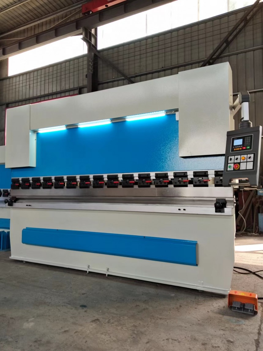
A bending machine is a mechanical device used for forming metal sheets. Its rear stop positioning system is a critical component for ensuring bending accuracy. The primary function of rear stop positioning is to control the feeding position of the sheet material, ensuring that the bending line aligns precisely with the mold center, thereby guaranteeing the accuracy and consistency of the bending angle. The following explanation will cover three aspects: Structural composition, working principle, and adjustment methods.
1, Structural Composition
The rear stop positioning system typically consists of four components: The stop frame, drive unit, measuring device, and control system. The stop frame is the component that directly contacts the sheet metal and is usually made of high-strength steel with a hardened surface to enhance wear resistance. The drive unit is responsible for moving the stop frame forward and backward, with common forms including servo motor drive and hydraulic drive. The measuring device is used to monitor the position of the material stop frame in real time, typically employing a linear encoder or encoder. The control system coordinates the operation of the drive unit and measuring device based on a pre-set bending program to ensure the material stop frame moves to the target position.
2, Working Principle
The core of the rear stop positioning system is position control. After the operator inputs the bending dimensions into the control system, the system calculates the target position of the stop frame based on the sheet metal thickness and die parameters. Upon receiving the command, the drive mechanism moves the stop frame. The measurement device continuously monitors the actual position of the stop frame and feeds the data back to the control system. The control system compares the actual position with the target position, adjusts the output of the drive mechanism to correct the deviation, and continues until the deviation falls within the allowable range.
The positioning accuracy of the material stop depends on the resolution of the measuring device and the response speed of the control system. High-precision linear encoders can control position detection accuracy to within 0.01 millimeters, while the rapid response of servo motors ensures that the material stopper reaches the designated position in a short time. Additionally, the rigidity of the material stopper also affects positioning stability. If the material stopper deforms under load, it can cause inaccurate positioning of the sheet material. Therefore, material stoppers are typically designed with reinforced structures to minimize deformation.
3, Adjustment Methods
The adjustment of the rear stop position can be done manually or automatically. Manual adjustment is suitable for small-batch production or debugging stages, where operators use buttons on the control panel to fine-tune the position of the stop frame and observe changes in the values on the scale or display screen. Automatic adjustment is the primary method used in mass production, where the control system automatically sets the position of the stop frame according to the program without human intervention.
During the adjustment process, it is important to note that the back gauge must remain parallel to the worktable to prevent sheet metal misalignment. The gauge surface should maintain complete contact with the sheet to avoid positioning errors caused by partial gaps. For longer sheets, auxiliary supports are necessary to prevent positioning inaccuracies due to material sagging.
Regular maintenance is essential for maintaining back gauge positioning accuracy. The sliding components should be kept clean and properly lubricated to minimize friction, while measuring devices must be protected from oil and dust contamination to ensure stable signal transmission. Additionally, the drive unit's transmission parts require regular inspection for wear, with damaged components needing prompt replacement.
The rear stop positioning system achieves precise control of sheet metal bending positions through the coordinated operation of mechanical, electrical, and control systems. Its structural design emphasizes rigidity and wear resistance, with a working principle based on closed-loop feedback control. Adjustment methods balance flexibility and efficiency. Proper operation and maintenance can extend equipment lifespan and ensure the stability of bending quality. Understanding the principles of rear stop positioning helps operators better use and maintain bending machines, thereby improving production efficiency and product quality.
If you are interested in bending machines, please contact us.
 Address:Room 1202, Detaitang Building, No. 118 Huaguang Road, Zhangdian District, Zibo, Shandong
 WhatsApp:+8615653328535
 Wechat: +8615965331535
  E-mail:zs@sdsmachinery.com
