 Language


More Language
Language
We are a professional bending machine manufacturer with over 10 years of industry experience. Today, we would like to introduce the functions and debugging methods of the bending machine rear stop system:
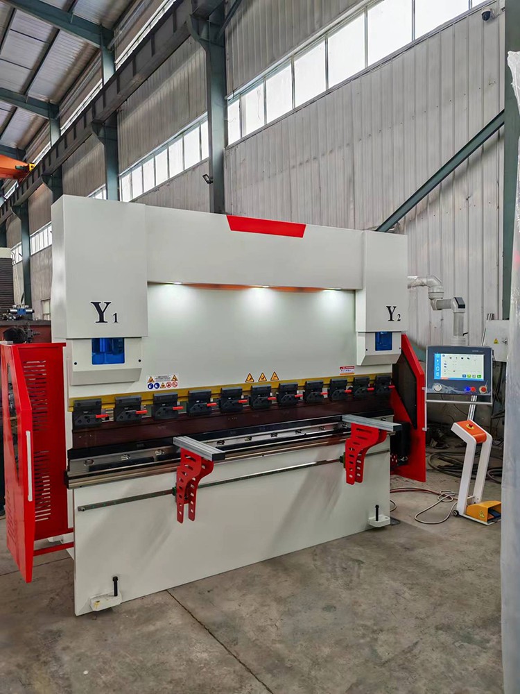
The rear stop system of a bending machine is a critical positioning device in sheet metal bending operations, primarily used to control the bending position and sequence of the sheet metal. This system achieves precise control over the forward/backward, left/right, and up/down movements of the stop fingers, ensuring that the sheet metal is accurately positioned during each bending operation. The basic functions of the rear stop system include positioning functionality, segmented bending functionality, and angle compensation functionality. The positioning function ensures that the relative position between the sheet metal edge and the mold center remains consistent during each bending operation; the segmented bending function enables multi-step bending of complex workpieces; and the angle compensation function automatically adjusts the positioning position based on material properties to compensate for dimensional deviations caused by springback.
Mechanical Structure Composition
The mechanical components of the rear stop system primarily consist of a base, crossbeam, stop finger mechanism, and drive unit. The base is mounted at the rear of the bending machine's workbench, providing structural support for the entire system. The crossbeam is arranged along the length of the machine tool and can move in the fore-and-aft direction. The stop finger mechanism is mounted on the crossbeam and can move left-right and up-down. The drive system typically employs a servo motor in conjunction with a ball screw or gear rack transmission to ensure positioning accuracy. Some high-end models are also equipped with a stop finger rotation function to accommodate the processing requirements of special-shaped workpieces. The rigidity of the mechanical structure directly affects the system's positioning stability, so the clearance between moving components must be strictly controlled.
Electrical Control System
The electrical control components of the rear stop system consist of a servo drive, encoder, limit switch, and control unit. The servo drive executes position commands and drives the axes to move precisely. The encoder provides real-time feedback on the actual position, enabling closed-loop control. The limit switch provides mechanical limit protection to prevent damage from overtravel. The control unit receives operating commands, coordinates the movement of the axes, and maintains communication with the main control system of the bending machine. Modern CNC systems typically integrate a rear stop control module, allowing parameters to be directly set via the human-machine interface. The system's response speed and repeatability accuracy are key indicators of electrical performance.
Basic Debugging Process
The debugging of the back gauge system should follow standard procedures. First, perform mechanical zero-point calibration to ensure accurate reference positions for each axis. Next, check the travel range of each moving axis and verify the effectiveness of the limit switches. Then, test the performance of individual axes, observing whether the operation is smooth and free from abnormal vibrations. After completing single-axis debugging, proceed with multi-axis coordinated motion testing to verify synchronization. Finally, conduct actual bending tests to check whether the positioning accuracy meets requirements. During the debugging process, all parameters should be recorded as baseline data for future maintenance. For initial debugging of new equipment or post-overhaul debugging, it is recommended that professional technicians perform the operation.
Positioning Accuracy Calibration Method
Positioning accuracy calibration is a critical step in the debugging process. X-axis (front-to-back direction) calibration typically involves using standard gauge blocks in conjunction with a dial indicator for measurement, with servo parameters adjusted to compensate for mechanical errors. Y-axis (left-to-right direction) calibration requires verifying consistency between each gear position, to ensure positional synchronization during parallel movement. Z-axis (vertical direction) calibration focuses on verifying the alignment of the lifting stroke with the set value. R-axis (rotational angle) calibration requires the use of an angle gauge to measure the actual rotation angle. During calibration, attention should be paid to the impact of temperature changes on measurement results; it is recommended to perform calibration after the equipment has been preheated and stabilized. For CNC systems, system errors can be corrected using parameter compensation functions to enhance overall accuracy.
Troubleshooting Common Faults
The rear stopper system may encounter various fault conditions during operation. Positioning deviation is the most common issue, which may be caused by mechanical loosening, improper servo parameters, or sensor malfunctions. Unusual noises during movement typically indicate wear on transmission components or inadequate lubrication. System shutdowns triggered by alarms require analysis of the alarm codes to determine the specific cause, with common causes including overload, overtravel, or communication interruptions. Asynchronous operation of the stopper fingers is often due to loose mechanical connections or inconsistent servo parameters. Poor electrical contact can cause abnormal position feedback, manifesting as positioning drift. When troubleshooting, follow the principle of starting with simple issues before moving to more complex ones. First, inspect mechanical connections and electrical wiring, then test sensor signals, and finally verify control parameters.
Key Points for Daily Maintenance
Daily maintenance of the rear material support system is critical to maintaining accuracy. The mechanical components should be inspected regularly to check the condition of fasteners and prevent loosening. The guide rails and lead screws should be kept clean and lubricated; it is recommended to use the specified type of grease. The electrical components should be checked for connector contact conditions to prevent oxidation. Limit switches should be ensured to trigger reliably. Servo motors should be kept well-ventilated to prevent overheating. Control system parameters should not be modified without professional guidance. After each maintenance session, a simple test should be conducted to confirm that all functions are operating normally. When the system is idle for an extended period, rust prevention measures should be implemented, and a comprehensive inspection should be conducted before resuming operation. It is recommended to establish maintenance records to track changes in equipment status.
Operating Precautions
Proper operation can extend the service life of the rear stopper system. Before starting the machine, check the movement range for any obstacles. When operating manually, pay close attention to the movement direction of each axis to avoid accidental collisions. During automatic operation, maintain a safe distance and be prepared to perform an emergency stop at any time. After replacing the mold, the material stop position must be recalibrated. When processing special materials, adjust the compensation value according to their springback characteristics. When the system issues an alarm, stop the machine immediately to investigate the issue; do not force continued operation. Overloading is strictly prohibited during daily operations, and frequent emergency starts and stops should be avoided. Operators must be familiar with the functions of each control key and strictly follow the operating procedures.
System Optimization Recommendations
The rear material support system can be optimized to improve performance. For mass production, a process parameter library can be established to reduce repetitive setup time. Frequently processed workpiece dimensions can be set as quick options to improve operational efficiency. Regularly back up system parameters to prevent data loss. Upgrading the control system software can provide new features and performance improvements. Adding auxiliary supports can reduce the deformation effects of long beams. Use high-precision measuring instruments for regular calibration to ensure long-term accuracy stability. The optimized system should undergo comprehensive testing and verification to confirm that all functions are normal and reliable.
The functionality and precision of a press brake backgauge system depend on proper calibration and maintenance. Understanding the system's components and operating principles facilitates quick diagnosis and resolution of abnormal conditions. A standardized calibration process ensures optimal system performance, while a scientific maintenance plan extends equipment lifespan. Despite the increasing functionality of backgauge systems with the advancement of CNC technology, the fundamental principles of calibration and maintenance requirements remain applicable. Operators and maintenance personnel must possess the necessary professional knowledge to fully utilize the equipment's capabilities and ensure production quality.
If you are interested in bending machines, please contact us.
 Address:Room 1202, Detaitang Building, No. 118 Huaguang Road, Zhangdian District, Zibo, Shandong
 WhatsApp:+8615653328535
 Wechat: +8615965331535
  E-mail:zs@sdsmachinery.com
