 Language


More Language
Language


一、Plate rolling machine
1,Machine model name
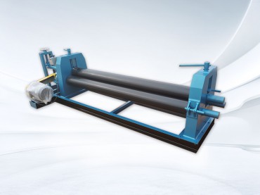
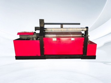
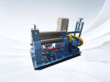
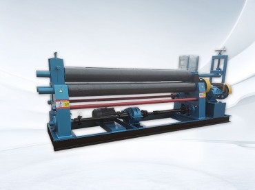
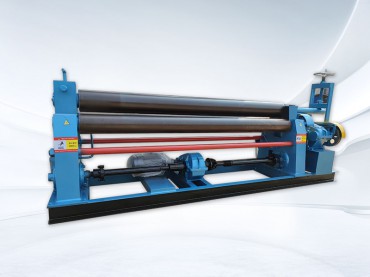
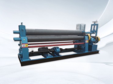
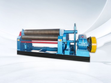
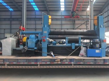
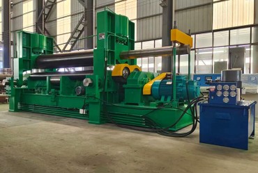
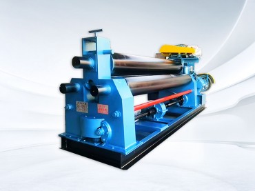
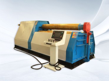
Model: W12-8x3000 CNC hydraulic four roll plate rolling machine
Image(For reference only):
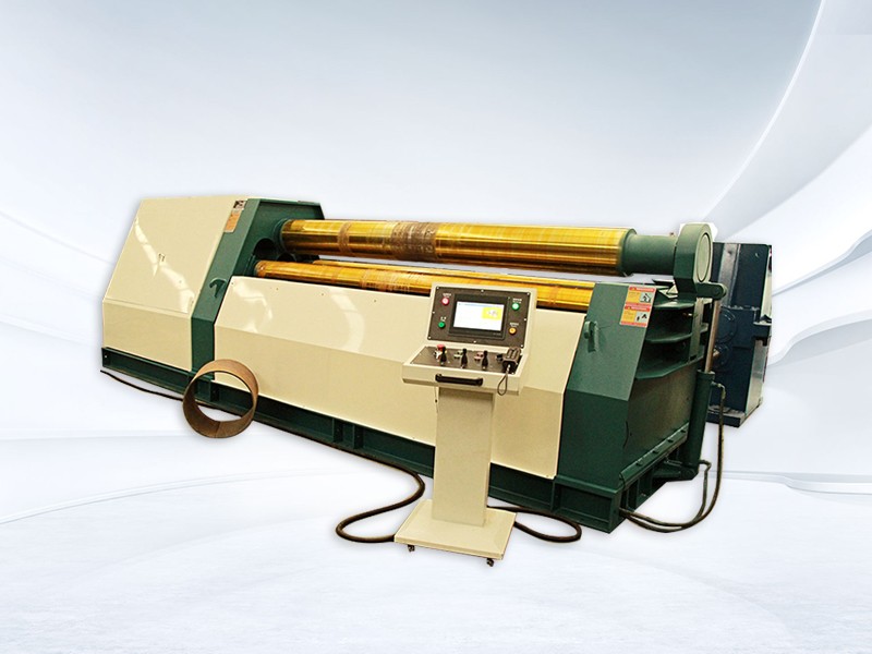
Machine Introduction
Plate rolling machine rolling process is a continuous three-point bending process of the plate, according to the different temperature of the roll can be divided into cold roll, hot roll and warm roll. It is mainly used for a certain thickness of metal plate bending into cylindrical, arc, rectangular and other curvature or variable curvature of mechanical equipment, metallurgy, building materials, petroleum, chemical industry, water conservancy and electricity, bridges, military, coal, mines, shipbuilding, boilers, aviation, power transmission equipment manufacturing industry, one of the necessary mechanical equipment.
The upper roller of the machine is the main driving roller, the main drive consists of hydraulic motor, planetary reducer, etc. The forward and reverse rotation of the motor realises the forward and backward movement of the plate, which mainly provides torque for the rolled plate to provide the plate. The equipment has measures to prevent the plate from slipping. Each motor is equipped with an instant brake, which enables the rolls to stop rotating accurately under the bending and rolling working condition, ensuring the precise positioning of the plate end, and preventing the steel plate from slipping off the machine and minimising the remaining straight edges.
The lower and side lifting are driven by hydraulic cylinders, fast speed lifting when unloaded, and slow speed lifting when loaded, which is more energy-saving for colleges and universities.
This model has superior performance and is easy to operate. With the pre-bending function of the end of the plate, the metal plate can be loaded at a time, without turning the head to complete the pre-bending of the end of the plate and the workpiece rolled into shape. The machine's control mode for digital control, the lower roller and side roller lifting using encoder detection, CRT display can directly observe the lower roller and side roller displacement, with simple operation, convenient, efficient and high advantages.
The electrical system adopts intelligent high-speed PLC produced by Wuxi XINJIE company, as well as the corresponding input and output modules and ‘XINJIE’ touch screen. The encoder adopts Taiwan ‘Germany BEBIK’ to detect the position, to ensure the precision of the position of the lower and side rollers and the lower rollers position monitoring; this configuration in the long term to the various users supporting the process has proved that: has a strong ability to resist interference, long service life, anti-vibration, stable operation and so on, suitable for such as humidity, high temperature, vibration, welding, open-air and other industrial environments, open air and other industrial environments.
The machine is equipped with digital display function, which mainly controls the synchronisation precision of the lower and side rollers, and at the same time monitors the pressures and displacements of the two master cylinders as shown on the digital display meters.
System power supply is three-phase AC 380V ± 20, 50Hz ± 5Hz.
Ambient temperature is -10~45℃.
Display accuracy is ≤±0.2mm.
When the position of working roller is controlled synchronously, the synchronisation accuracy is ±0.2mm.
2, Main parameters
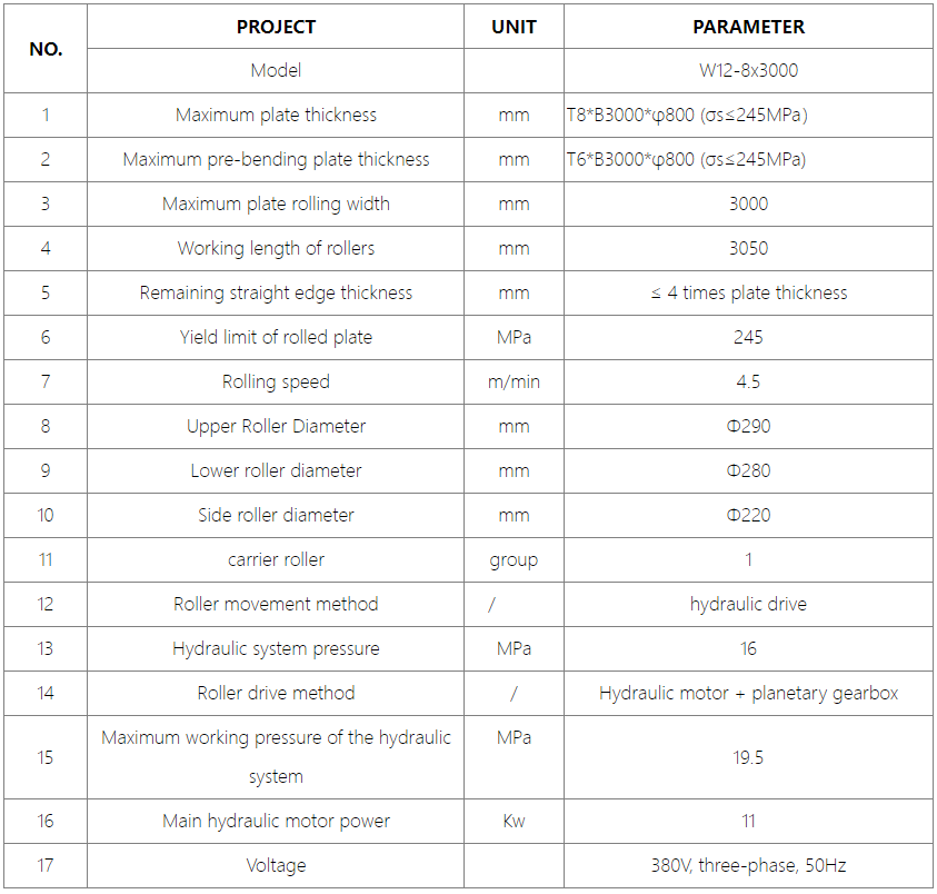
❄Our machine's standard voltage is 380V, three-phase, 50Hz. If the voltage is different, please let us know and the price may change.
3, Structure and performance
1.Tipping cylinder 2.Tipping head frame 3.Left frame 4.Upper roller 5.Side roller 6.Lower roller 7.Right frame 8.Balancing device 9.Upper Roller Driving Device 10.Lower Roller Driving Device 11.Side Roller Cylinder 12.Lower Roller Cylinder 13.Base (14.Side Supporting [optional] 15.Top Supporting System [optional] 16.Feeding Electric Roller Conveyor [optional]) 17.Hydraulic System 18.Electric Control System
3.1 Structural overview:
The basic structural form of the machine: the machine is mainly composed of frame part, upper roller part, lower roller part, side roller part, flip bearing body part, main transmission part, hydraulic part, electrical part, lubrication part, foundation part and so on.
The left and right racks of the machine are mounted on an integral base, which constitutes the main body of the machine. The left end bearing body of the upper roller is mounted into the turning bearing body, and the right end bearing body is mounted in the right side frame.
The upper roll of the machine is the main driving roll, which is directly connected to the driving roll by a hydraulic motor through a planetary reducer. The upper roller is fixed in position and only carries out rotary motion; the working roller carries out both rotary motion and lifting motion.
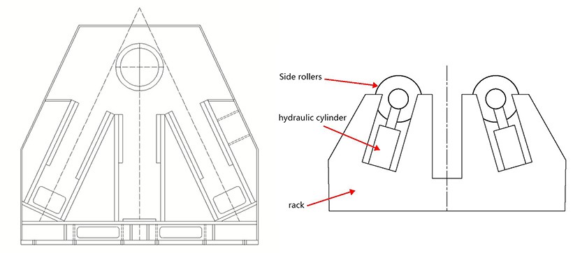
The machine lower roller cylinder, side roller cylinder were installed in the left and right frame of the guide groove, the reciprocating motion of the cylinder, can make the lower roller and side roller along the guide groove up and down, but also can be tilted movement, so that the roll of the conical workpiece and the workpiece correction and rounding convenient.
There is a turning bearing body on the left frame, which can be driven by the turning cylinder to realize the opening and closing with the head of the upper roller; there is a balancing device on the tail of the upper roller, which can realize the balancing and warping of the upper roller when the upper roller is opened with the inverted head frame.
The movement of the work rolls is guided by high quality linear slides.
The control of the machine is centralized on the main operating table.
3.1.1 Work rollers
One of the most important components of the coiler, its quality and performance of the advantages and disadvantages directly affect the service life of the coiler and the precision of the roll.
(1)Material of work rolls
The upper and lower work rolls are made of high-strength roll steel, which are completed by multiple procedures such as forging, tempering, quenching, tempering, stress relief and precision lathe machining (Note: the processing procedures of the rolls are different according to the different needs of the users); it strictly ensures that the work rolls have a high contact strength on the surface, and the surface of the rolls is free of indentation when rolling the steel sheet material, and it can satisfy the requirements of rolling the steel sheet for a long period of time.
(2)Rotation of the work rollers: the hydraulic motor is connected to the planetary gearbox, which in turn transmits the torque to the work rollers.
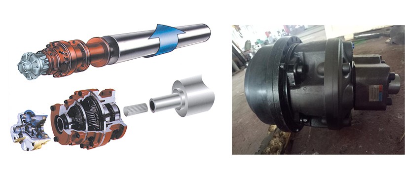
The four-roller plate rolling machine for the upper roller drive: the upper roller for the drive roller (as shown below), the upper roller independent hydraulic motor and the use of high-power planetary reduction gearbox directly coupled connection (linear), not through the intermediate gear transmission, which is the most energy-saving drive mode.
(3)Movement of work rollers
According to the movement mode of the working roller (side roller) of the plate rolling machine, linear sliding rail technology is adopted.
3.2 Bearings at the ends of the work rollers
All work rollers have two roller bearings at each end, and the roller bearings are domestic famous brand products.
Each roller of the four-roller plate rolling machine adopts the industry-recommended very durable spherical roller bearings.
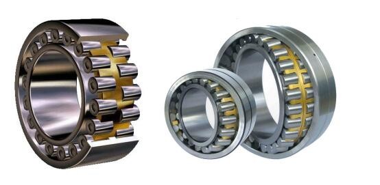
The product is adopted on each roller to be able to well offset the pressure caused by the shaft deflection during the rotation of the roller.
The risk of scratches and cracks on the rollers is avoided due to the free and flexible movement of each shaft.
The internal design of this adjustable bearing allows it to withstand deflections and tilts of the roller bar. This collapsible movement avoids reverse forces causing damage to the rollers when it is fixing the outer cover forces.
The advantage of this type of bearing is that it moves smoothly and safely along the tilting table of the roller shaft and eventually returns to its original position, regardless of the direction of shaft deflection.
The relative requirements of a tapered roll plate are much more demanding, as it requires the roller shaft to be able to tilt, and the load this places on the roller shaft is not well balanced.
3.3 Racks and Bases
The frame and seat of this plate rolling machine are made of domestic Q235A high-quality steel, which is CNC-cut, polished and welded, and then the welded structural parts are sent to professional heat-treatment manufacturers for stress-relief annealing treatment. All records of workpieces are incorporated into the quality tracking system.
Clamping pressure can be set:
The clamping force between the upper and lower rolls can be pre-set for different product rolling process requirements, effectively preventing excessive pressure indentation on softer materials.
The clamping force is controlled by the relief valve of the hydraulic station.
Top support system:(Optional accessories)
The center bracket, or top bracket, is mounted on the rear fuselage.
It consists of a removable bracket. The bracket can be moved from the top to the bottom according to the size of the cylinder and supports the cylinder during the winding stage. The center support has a tie rod fixed to the ground. The user must arrange anchoring points on the foundation.
The center support can be controlled hydraulically and electrically.
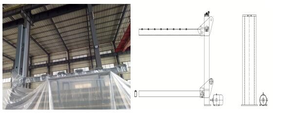
Figure 2.13: Center stand
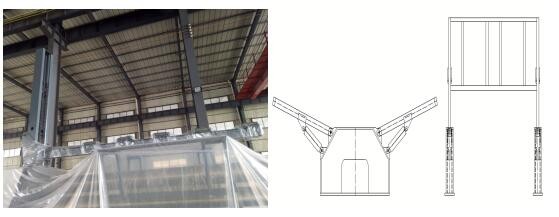
Left and right support system: (Optional accessories)
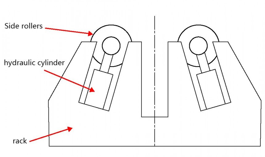
Hydraulic support on both sides: It is used to support the large-diameter cylinder on both sides to prevent the steel plate from collapsing under its own weight in the process of rolling, resulting in poor rolling accuracy. Both sides of the hydraulic support have multiple rows of rollers, each side can be two segments to move, in order to better support the cylinder. The hydraulic support can be used as a raceway when the hydraulic support is released, and the hydraulic support on the feeding side is equipped with an axial hydraulic actuator.
Motorized feeding platform (Optional accessories)
Composed of rollers, motors, reducers, hydraulic cylinders, etc., used to hold and feed the steel plate to be rolled. Transporting and adjusting the steel plate to the coiler industry for processing.
3.4Hydraulic system description
The machine system is designed as an independent oil circuit, which is functioned by two parts, one part is the main transmission part: to provide power for the upper and lower work rollers: one part is the auxiliary transmission: to provide power for the lifting of the lower and side work rollers; and the overturning of the inverted head. Each oil circuit is driven by a motor to a high-pressure oil pump for systematic independent oil supply, and adopts the stacked valve structure, which is characterized by:
Reduced space for device and installation;
No special installation skills are required and hydraulic systems can be added or changed quickly and easily;
avoiding the use of split collector valve synchronization system, which is susceptible to pressure inconsistencies between the two cylinders.
Overcoming the problems of leakage, vibration and noise when piping is connected, increasing the reliability of the hydraulic system;
Easy maintenance and inspection due to the composition of stacked components.
Each oil circuit by two relief valves to control the pressure, the highest set pressure of each oil circuit is 25MPa, mainly to control the pressure of the main cylinder, the other relief valve set pressure of 16MPa, mainly to control the pressure of the tipping cylinder and the balance cylinder.
The main cylinder in each oil circuit consists of two sets of superimposed elements to regulate the movement speed of the main cylinder to meet the different working speeds of the side and lower rolls.
In order to ensure the synchronization accuracy of the main cylinder at both ends of each moving work roll, the left and right racks and tipping frame are equipped with high-precision displacement sensors, and through the pressure sensors, the microcomputer control system carries out the detection and adjustment of the movement of the piston of the main cylinder to achieve the synchronization accuracy requirements at both ends of the work roll.
a.The unique pre-pressurization technology is adopted to effectively avoid hydraulic shock and improve the life of pipeline and sealing.
b. Hydraulic components are selected from Yuji “Yuken” high quality products to ensure the stability of the hydraulic system.
c. Each input and output port of the hydraulic system is set up with corresponding detection points, which is convenient for maintenance and fault checking, and the oil pump adopts the lower type and positive pressure oil suction. At the same time, the filter, level meter, are with a signaling device, can automatically alarm fault tips. The other hydraulic station is independent of the machine base, maintenance, maintenance is convenient; and away from the heat source.
d, system production in strict accordance with the national standard, the implementation of the standard, pipe curve radius is reasonable, and not less than 90 °, smooth transition, a reasonable arrangement of vibration damping pipe clamps, effectively avoiding the impact, vibration. Ensure that the hydraulic pipeline has no impact, vibration.
e. The system design gives full consideration to high efficiency and energy saving, reduces the power waste, and reduces the heat source.
3.5 Lubrication system
The lubrication system of this machine, such as linear slide, work rollers and other lubrication, adopts both centralized lubrication and manual lubrication at points.
3.6 Control systems
1. The micro-control system includes hardware parts such as main electric cabinet, control cabinet and special control software.
2. The system has two sets of operating systems: touch screen control and manual control, which can be easily converted.
The sensor adopts American or Italian brand products to ensure the position accuracy and realize the position monitoring of each work roll.
3. Main technical indexes:
Average trouble-free time: ≥20,000 hours
Display precision: ≤±0.2mm
When the lower roller lifting, side roller tilting lifting displacement synchronization control, synchronization accuracy: ≤ ± 0.2mm
Sensor displacement resolution: ≤0.1mm
4. Micro-control system core composition and control principle.
Four-roller coiler consists of industrial control computer, Japan XINJIE programmable controller (PLC) and its digital, analog expansion module and its peripheral circuits, displacement sensors and other components.

The industrial control computer communicates with XINJIE programmable controller through special communication cable to get the data of lower roller displacement, displacement of front and rear side roller Ⅰ and Ⅱ cylinders, hydraulic pads Ⅰ and Ⅱ, balance cylinder, tipping cylinder, etc., and input and output status of PLC.
The computer and PLC synthesize the above information, and after intelligent processing, control the PLC output, through the intermediate relay, control the peripheral electrical appliances, control the operation of the motor, the switch of the hydraulic valve, to achieve the normal operation of the control system and to maintain the accuracy of the system operation. At the same time, the computer control system will display various data and information such as displacement, alarm, output status, etc. on the computer screen in a graphic and text combination.
Control system function: PLC system can display a variety of real-time data and rolled plate information.
This system has advanced design, good operation performance, safe and reliable operation, good fault tolerance performance, with the following functions.
Fault self-diagnosis display and intelligent judgment function of operation error
Real-time display of absolute position of both ends of the rear side rollers.
Real-time display of absolute position of both ends of the lower roller
Real-time display of the tilting amount (degree) of the front and rear side rollers and both ends of the lower roller.
Soft and hard limit position protection function for each moving part;
Power failure memory function: that is, when the operation in the middle of a sudden power failure or the end of the rolled plate machine power failure, due to some reasons the upper and lower rollers position changes, in the re-energized, the PLC system automatically tracking, accurate and error-free display of the actual position.
Safety protection function: when an unexpected situation occurs, the operator can easily and timely shut down the equipment and system to ensure the safety of equipment and personnel life.
Control function:
The industrial control computer communicates with XINJIE programmable controller through a special communication cable to get the data of four displacements of the side rollers at the front and back sides, PLC input and output status. The computer and PLC synthesize the above information, through intelligent processing, control PLC output, through the intermediate relay, control peripheral electrical appliances, control the operation of the motor, the switch of the hydraulic valve, to achieve the purpose of controlling the normal operation of the system.
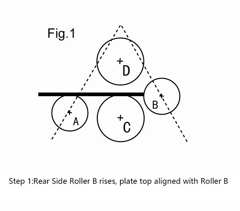
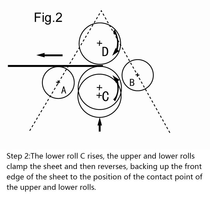
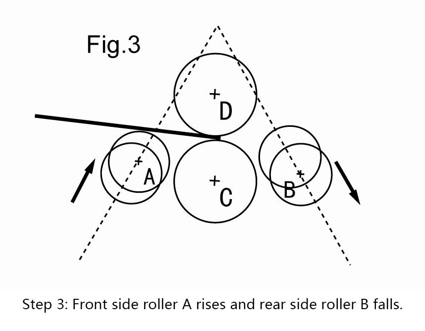
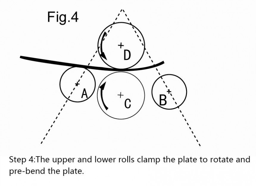
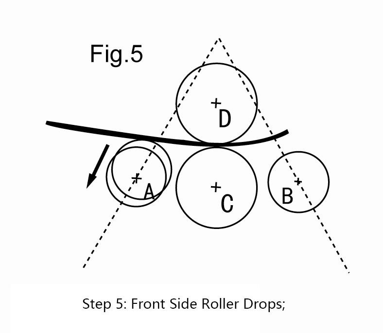
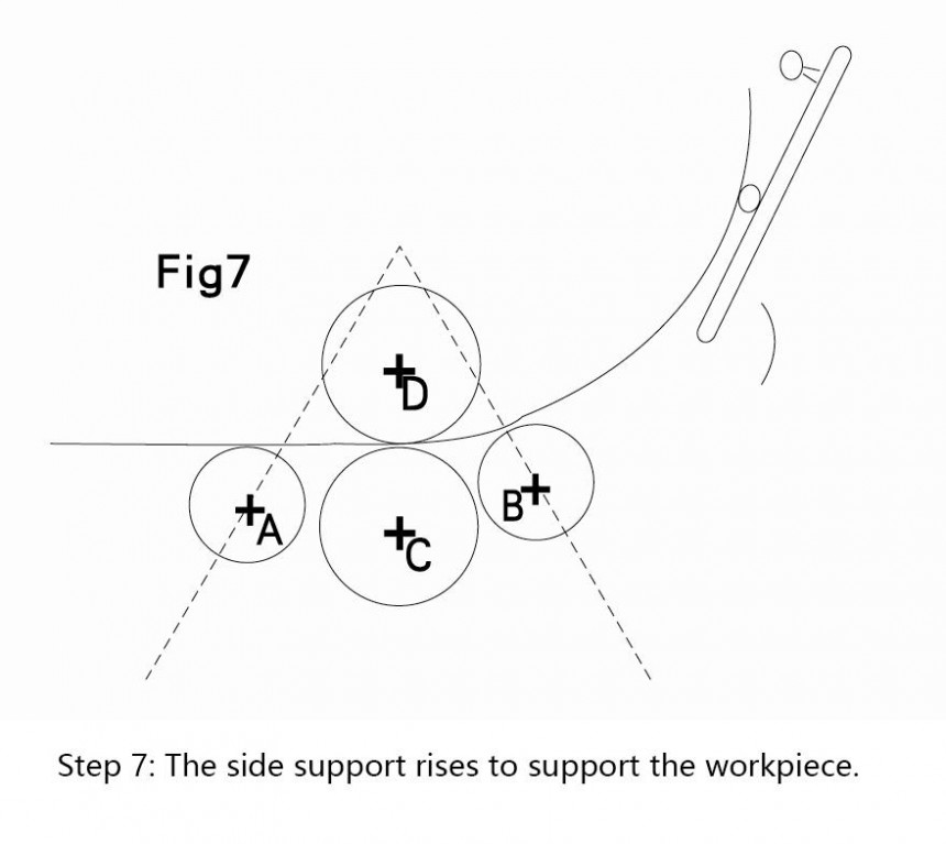
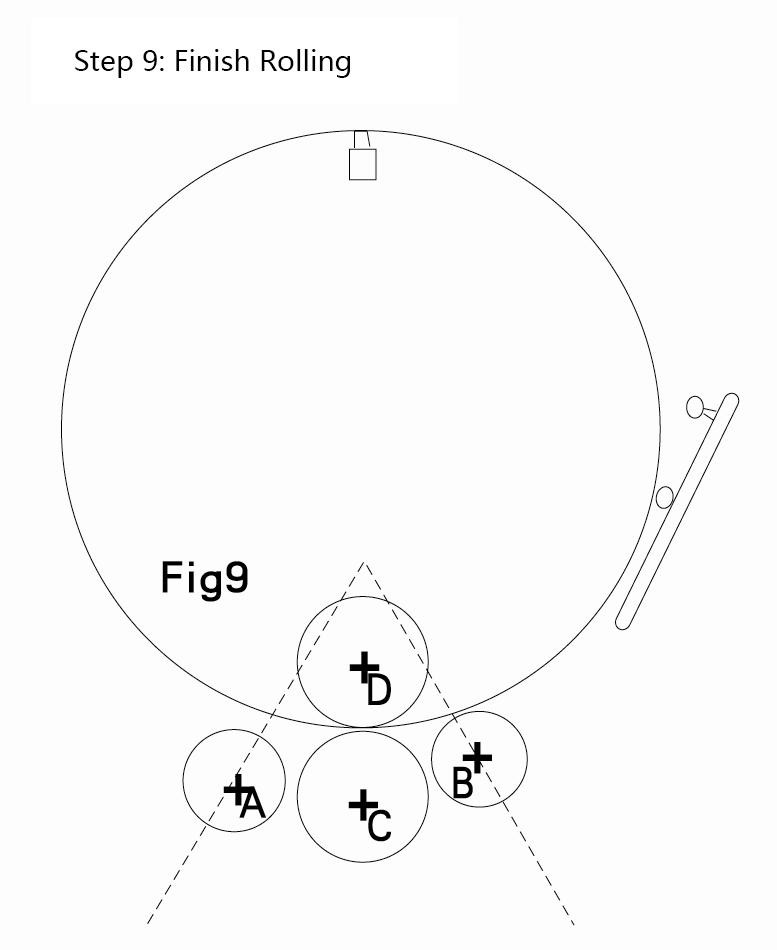
4,Rolling flow chart


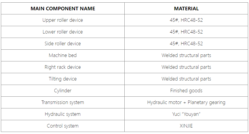
5, List of Main Components
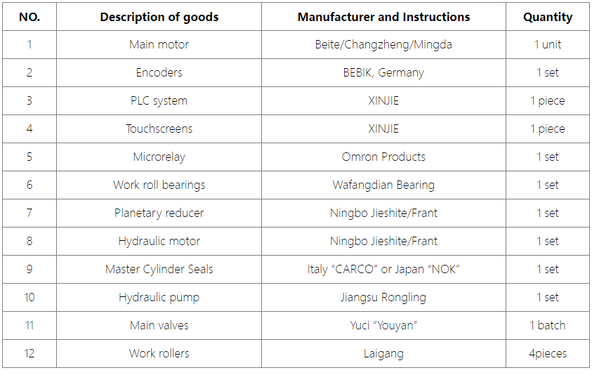
6, Details of Purchased/Outsourced Parts
 Address:Room 1202, Detaitang Building, No. 118 Huaguang Road, Zhangdian District, Zibo, Shandong
 WhatsApp:+8615653328535
 Wechat: +8615965331535
  E-mail:zs@sdsmachinery.com