
Professionalism stems from dedication. For over a decade, we have been committed to the manufacturing of plate rolling machine production lines. Here, we introduce common fault diagnosis methods for the electrical systems of plate rolling machines:
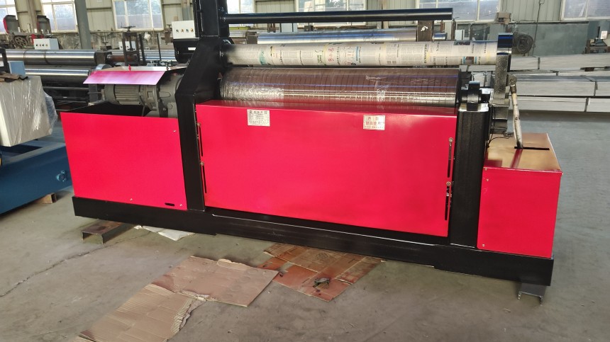
As an essential piece of equipment for metal sheet processing, the stability of a plate rolling machine's electrical system directly impacts processing accuracy and equipment lifespan. Electrical system faults are characterized by their high degree of concealment, necessitating the use of systematic diagnostic methods. This article will introduce fault diagnosis methods for roll forming machine electrical systems from three aspects: fault phenomenon identification, use of detection tools, and typical fault handling.
1, Identification of fault phenomena
Electrical system faults are usually manifested through abnormal phenomena. Operators should first pay attention to abnormal conditions during equipment operation, including issues such as difficulty starting motors, unstable speed, or sudden shutdowns in the power system; abnormal PLC indicator lights or display errors on touchscreens in the control system; and circuit breaker tripping or poor contactor engagement in the distribution system. These phenomena often correspond to specific fault types, such as motor overheating caused by overload or winding short circuits, or control signal interruptions related to loose wiring.
Recording equipment operating parameters is particularly important for fault diagnosis. Operators should regularly check the readings on voltmeters and ammeters to see if they exceed the normal range. Fault codes displayed by variable frequency drives and alarm messages from PLCs are clear indicators and should be recorded promptly and interpreted in accordance with the equipment manual. Sound and smell are also important criteria for diagnosis. Electrical components that have short-circuited often produce abnormal noises and a burning smell.
2, Use of testing tools
A multimeter is a basic electrical testing tool. When measuring voltage, be sure to select the appropriate range, first test the power input terminal, and then gradually measure the voltage of each branch. Before measuring resistance, be sure to turn off the power and focus on checking whether the circuit is open or closed and whether the component resistance is normal. A megohmmeter is used to test the insulation performance of motor windings and cables. If the measured value is lower than 1MΩ, there is a safety hazard.
An oscilloscope can be used to observe the waveform characteristics of control signals. When encoder signals are abnormal, an oscilloscope can be used to visually identify pulse loss or distortion. Timing detection of PLC input and output signals also requires the use of an oscilloscope, which can identify issues such as signal delay or jitter. For variable frequency drive systems, current clamp meters can be used to non-contact measure the three-phase current of motors, quickly determining whether there is a phase loss or imbalance.
3, Typical fault handling
Power supply failure is the most common electrical problem. When the equipment cannot be powered on, check the main power switch, circuit breaker, fuse, and other protective components in order. When the control system malfunctions, first confirm that the PLC power supply is normal, and then check the status of the I/O module indicator lights. If the touch screen does not display but the PLC is running normally, it may be a fault in the display power supply or communication line.
Motor-related faults require step-by-step troubleshooting. If the motor fails to start, first check the voltage of the contactor coil, then measure the resistance of the motor windings. When the variable frequency drive (VFD) alarms, determine whether the issue stems from incorrect parameter settings or hardware failure. If the alarm persists after resetting, inspect the power modules. Sensor faults can cause position control failure. Photoelectric switches can be tested using the light-blocking method, while proximity switches can be checked by observing changes in the indicator light when a metal object is brought near.
Circuit issues are often hidden faults. Cable insulation damage may cause intermittent short circuits, requiring segmented troubleshooting. Loose terminal blocks can increase contact resistance, resulting in intermittent fault characteristics. Signal interference issues often occur after new equipment is added and can be resolved by installing magnetic rings or adjusting the wiring configuration.
Regular maintenance can effectively prevent electrical faults. Electrical connection terminals should be tightened once a month, control cabinets should be cleaned of dust every quarter, and ground resistance should be tested annually. Stockpiling spare parts is also important; consumables such as AC contactors and fuses should be kept in inventory. After fault resolution, detailed records of symptoms, test data, and resolution methods must be documented to form a complete maintenance file.
Mastering systematic diagnostic methods can significantly improve maintenance efficiency. In actual operation, it is important to adhere to the principle of proceeding from simple to complex, first checking obvious fault points and then thoroughly investigating hidden issues. Safety regulations must be strictly followed; insulated tools must be used for live testing, and high-voltage testing must be performed by two people working together. With the development of intelligent equipment, it is necessary to not only master basic electrical knowledge but also continuously learn new diagnostic techniques.
If you are interested in plate rolling machines, please contact us.
 Address:Room 1202, Detaitang Building, No. 118 Huaguang Road, Zhangdian District, Zibo, Shandong
 WhatsApp:+8615653328535
 Wechat: +8615965331535
  E-mail:zs@sdsmachinery.com


